
CAD, CAM and CNC: How Modern Manufacturing Uses Mechanical Engineering
Modern manufacturing has changed dramatically with the introduction of digital design, automation and computer-controlled machines. Products that once required extensive manual drafting and machining can now be designed, programmed, simulated and manufactured with remarkable accuracy. At the centre of this transformation are CAD, CAM and CNC technologies. Together, they connect mechanical engineering design with modern manufacturing. CAD helps engineers create and modify digital designs, CAM converts those designs into manufacturing instructions, and CNC machines use those instructions to manufacture physical components.
For mechanical engineering students, understanding how CAD, CAM and CNC work together provides valuable insight into the way modern factories design and produce everything from automobile components to industrial machinery.
What Are CAD, CAM and CNC?
Although CAD, CAM and CNC are closely related, each technology performs a different role in the manufacturing process.
CAD – Computer-Aided Design
CAD stands for Computer-Aided Design. It allows engineers and designers to create accurate two-dimensional drawings and three-dimensional models using computers.
Instead of creating every drawing manually, engineers can digitally develop components, assemblies and complete products.
CAD is commonly used for:
-
2D engineering drawings
-
3D modelling
-
Machine component design
-
Product development
-
Assembly design
-
Engineering documentation
-
Design modification
-
Prototyping
Popular CAD software includes AutoCAD, CATIA, SolidWorks, Siemens NX, Creo and Fusion 360.
For mechanical engineering students, CAD is an important skill because modern product development increasingly begins with a digital model.
CAM – Computer-Aided Manufacturing
CAM stands for Computer-Aided Manufacturing. It uses computer software to help plan and control manufacturing operations.
A CAD model describes what a component should look like. CAM helps determine how that component can be manufactured.
CAM software can assist with:
-
Toolpath generation
-
Cutting operations
-
Machining strategies
-
Tool selection
-
Production planning
-
CNC programming
-
Manufacturing simulation
This creates an important connection between engineering design and physical production.
CNC – Computer Numerical Control
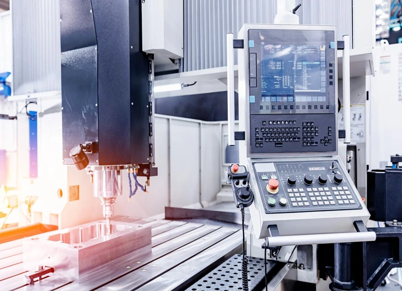
CNC stands for Computer Numerical Control. CNC machines use programmed instructions to control machining operations.
Instead of relying entirely on manual control, the machine can automatically control movements such as cutting-tool position, speed and feed according to programmed instructions.
Common CNC machines include:
-
CNC milling machines
-
CNC turning machines
-
CNC machining centres
-
CNC routers
-
CNC grinders
-
CNC EDM machines
CNC technology allows manufacturers to produce complex components with high repeatability and accuracy.
How CAD, CAM and CNC Work Together
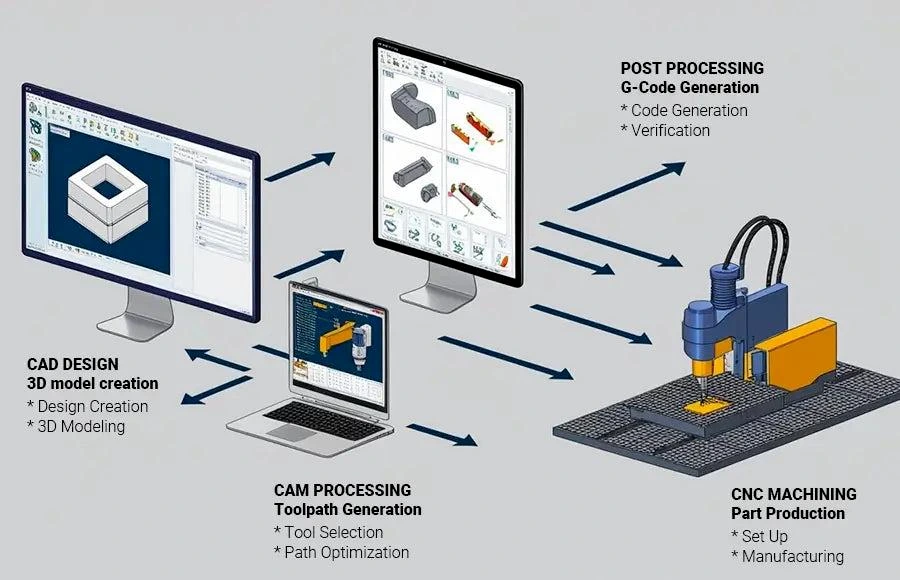
The real strength of CAD CAM CNC technology comes from the way these systems work as part of a connected manufacturing workflow.
A simplified process looks like this:
Design → CAD Model → CAM Planning → CNC Programming → Machining → Inspection
Step 1: Product Design
The engineer first understands the product requirements and creates a digital model using CAD software.
Step 2: Engineering Analysis
The design may be checked for dimensions, material requirements, strength, manufacturability and other engineering considerations.
Simulation tools can also be used where appropriate.
Step 3: CAM Preparation
The CAD model is imported into CAM software. The manufacturing engineer selects suitable machining operations and generates toolpaths.
Step 4: CNC Programming
The required machine instructions are generated and prepared for the CNC machine.
Step 5: Machining
The CNC machine performs the programmed operations using appropriate cutting tools and machining parameters.
Step 6: Inspection
The finished component is measured and inspected to determine whether it meets the required dimensions and quality standards.
This digital workflow can significantly reduce errors between design and manufacturing.
Types of CAD Used in Mechanical Engineering
CAD applications can be broadly divided into different categories depending on their purpose.
2D CAD
2D CAD is commonly used for engineering drawings, layouts, dimensions and manufacturing documentation.
3D CAD
3D CAD allows engineers to create detailed three-dimensional models of components and assemblies.
Parametric CAD
Parametric modelling allows designers to modify dimensions and relationships while maintaining design intent.
Surface Modelling
Surface modelling is useful when designing complex shapes and products with curved surfaces.
For students, learning both engineering drawing fundamentals and 3D CAD modelling can provide a strong foundation for mechanical design.
Types of CNC Machines
CNC technology covers a wide range of manufacturing equipment.
CNC Turning
CNC turning is commonly used to manufacture cylindrical components such as shafts, bushes and pins.
CNC Milling
CNC milling can produce slots, pockets, holes, profiles and complex surfaces.
CNC Machining Centres
Machining centres can combine several operations in a single automated setup.
CNC Grinding
CNC grinding can be used when high surface quality and dimensional accuracy are required.
CNC EDM
Electrical Discharge Machining can be used for machining certain hard or complex materials where conventional cutting may be difficult.
The choice of machine depends on the material, component geometry, production volume and required accuracy.
Why CAD, CAM and CNC Are Important in Modern Manufacturing
The integration of CAD CAM CNC has transformed the relationship between design and manufacturing.
Some important benefits include:
Improved Accuracy
Digital design and computer-controlled machining can help manufacturers achieve precise dimensions and consistent results.
Better Repeatability
Once a CNC process has been properly developed and verified, the same machining process can be repeated for multiple components.
Faster Product Development
Digital models can be modified more easily than manually created drawings, allowing engineers to make design changes quickly.
Reduced Manufacturing Errors
Digital workflows can reduce the possibility of certain manual transcription and programming errors, particularly when properly integrated and verified.
Complex Component Manufacturing
Modern CNC machines can manufacture shapes and features that would be difficult or impractical to produce manually.
Better Production Efficiency
Automation can reduce repetitive manual operations and improve production consistency.
Easier Design-to-Manufacturing Integration
CAD and CAM create a digital link between product design and manufacturing planning.
Role of Mechanical Engineers in CAD, CAM and CNC
Mechanical engineers play an important role at almost every stage of this process.
A mechanical engineer may be involved in:
-
Designing machine components
-
Creating engineering drawings
-
Developing 3D models
-
Selecting materials
-
Checking manufacturability
-
Preparing manufacturing processes
-
Developing CNC programs
-
Selecting cutting tools
-
Optimizing machining parameters
-
Inspecting finished components
-
Improving production processes
This is why CAD CAM CNC knowledge can be particularly valuable for mechanical engineering students who want to work in design, manufacturing or production.
Skills Mechanical Engineering Students Should Develop
Students interested in CAD, CAM and CNC should develop both theoretical knowledge and practical skills.
Important areas include:
Engineering Drawing
Students should understand dimensions, tolerances, sectional views, projections and engineering drawing standards.
3D Modelling
Learning a professional CAD package can help students develop practical design capabilities.
Manufacturing Processes
Students should understand machining, casting, forming, welding and other manufacturing processes.
CNC Programming
Basic knowledge of CNC programming and machine operation helps students understand how digital designs become physical components.
CAM Software
Students should learn how toolpaths are generated and how machining strategies affect production.
Metrology
Measurement and inspection are essential for determining whether manufactured components meet specifications.
Problem-Solving
Manufacturing frequently involves challenges involving tooling, material, tolerances, surface finish, machine parameters and production efficiency.
Applications of CAD, CAM and CNC
These technologies are used across many industries.
Automobile Industry
CAD, CAM and CNC are used for designing and manufacturing engine components, transmission parts, tooling, fixtures and other vehicle components.
Aerospace Industry
Aircraft components often require precise engineering, lightweight structures and strict quality control.
Medical Equipment
Computer-controlled manufacturing can be used to produce precision components for medical devices and equipment.
Consumer Products
Manufacturers use CAD and CNC technologies for product development, moulds, tools and precision components.
Heavy Engineering
Industrial machinery and heavy engineering products frequently require accurate design and manufacturing processes.
Tool and Die Manufacturing
CAD/CAM systems are particularly important for developing moulds, dies and precision tooling.
CAD, CAM and CNC in Industry 4.0
The development of Industry 4.0 is taking digital manufacturing even further.
Modern manufacturing systems increasingly combine:
-
CAD
-
CAM
-
CNC
-
Robotics
-
Industrial IoT
-
Sensors
-
Data analytics
-
Digital twins
-
Automated inspection
-
Cloud-based manufacturing systems
This creates increasingly connected production environments.
For example, a manufacturing facility may collect data from CNC machines and use it to monitor production performance, identify machine problems and improve manufacturing efficiency.
Mechanical engineering students who understand CAD, CAM and CNC alongside automation and digital technologies can therefore be better prepared for modern manufacturing careers.
Practical Learning for Mechanical Engineering Students
CAD, CAM and CNC are best understood through practical exposure.
Students can develop their skills by:
-
Learning engineering drawing fundamentals.
-
Creating 2D drawings using CAD software.
-
Developing 3D component models.
-
Designing assemblies.
-
Learning basic manufacturing processes.
-
Understanding CNC machine operations.
-
Creating simple CAM toolpaths.
-
Working on manufacturing projects.
-
Measuring finished components.
-
Comparing the digital design with the manufactured product.
At Ideal Institute of Engineering, Kalyani, mechanical engineering students have access to practical learning facilities covering areas such as computer-aided machine drawing, manufacturing technology, metrology and machine tools.
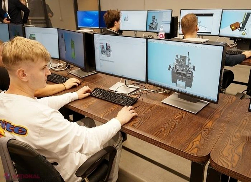
The Computer Aided Machine Drawing Laboratory provides students with exposure to CAD applications including AutoCAD and CATIA, along with 2D drafting and 3D modelling.
Such practical exposure helps students understand that mechanical engineering is not limited to classroom theory. It involves designing, analysing, manufacturing, measuring and improving real engineering products.
Career Opportunities with CAD, CAM and CNC Skills
Students who develop strong CAD CAM CNC skills can explore careers such as:
-
CAD Design Engineer
-
Mechanical Design Engineer
-
CAD/CAM Engineer
-
CNC Programmer
-
Manufacturing Engineer
-
Production Engineer
-
Tool Design Engineer
-
Process Engineer
-
Quality Engineer
-
Product Development Engineer
-
Manufacturing Automation Engineer
-
CNC Machine Operator or Programmer
With additional skills in simulation, robotics, automation and programming, graduates can also explore broader Industry 4.0 roles.
What Should Students Learn First?
Students often wonder whether they should start with CAD, CAM or CNC.
A practical learning sequence is:
Engineering Drawing → CAD → Manufacturing Processes → CNC Fundamentals → CAM → Advanced Manufacturing
This sequence helps students understand the relationship between design and production.
However, the exact learning path can vary depending on the student’s career objective.
Someone interested in product design may focus more heavily on CAD and simulation, while someone interested in manufacturing may spend more time learning CNC, CAM, tooling and production processes.
Future of CAD, CAM and CNC
The future of manufacturing is becoming increasingly digital.
CAD systems are becoming more intelligent, CAM software is becoming more sophisticated and CNC machines are becoming increasingly connected with factory networks and automation systems.
Artificial intelligence, generative design, additive manufacturing, digital twins and smart inspection technologies are likely to further influence manufacturing workflows.
For mechanical engineers, this means that traditional manufacturing knowledge will remain important, but digital skills will become increasingly valuable.
Frequently Asked Questions About CAD, CAM and CNC
What are CAD, CAM and CNC?
CAD is Computer-Aided Design, CAM is Computer-Aided Manufacturing, and CNC is Computer Numerical Control. Together, they connect digital engineering design with computer-controlled manufacturing.
Why are CAD CAM CNC important for mechanical engineering?
CAD, CAM and CNC help mechanical engineers design products, plan manufacturing processes and produce components accurately and consistently.
Is CAD difficult for mechanical engineering students?
CAD can be learned progressively. Students who understand engineering drawing and mechanical design fundamentals can usually develop CAD skills through regular practice and project work.
What is the difference between CAD and CAM?
CAD is primarily used to create and modify engineering designs, while CAM uses digital design information to plan manufacturing operations and generate machine toolpaths.
What is the difference between CAM and CNC?
CAM software helps generate manufacturing instructions and toolpaths, while a CNC machine uses programmed instructions to control its machining operations.
Which CAD software should mechanical engineering students learn?
Students can consider software such as AutoCAD, CATIA, SolidWorks, Creo or Siemens NX. The most appropriate choice depends on academic requirements and the industries they want to enter.
Do mechanical engineers need to learn CNC programming?
Basic CNC knowledge is highly useful for students interested in manufacturing, production, tooling and machining. It helps them understand how digital designs are converted into physical components.
Can CAD CAM CNC skills help with employment?
Yes. CAD, CAM and CNC skills can support careers in mechanical design, manufacturing, production, tooling, CNC programming, quality control and product development.
Conclusion
CAD CAM CNC technologies have become an important part of modern mechanical engineering and manufacturing. CAD allows engineers to create accurate digital designs, CAM helps convert those designs into manufacturing processes, and CNC machines turn programmed instructions into physical components.
For mechanical engineering students, learning this complete workflow provides more than software knowledge. It develops an understanding of how engineering ideas move from a concept on a computer screen to a finished product.
As manufacturing moves toward Industry 4.0, smart factories and increasingly automated production systems, students who combine strong mechanical engineering fundamentals with CAD, CAM, CNC, automation and digital skills can be better prepared for the future.
The best time for students to begin developing these skills is during their engineering education—through laboratory practice, projects, software training, internships and hands-on exposure to real manufacturing processes.